The current-loop interface
revised november 2010
Connecting a computer with a terminal (or any other peripheral) via a current loop was very common in the 70's. The current loop was largely superseded by the EIA/CCITT voltage-level interface in the 80's.A current loop is a closed circuit through which no current flows in the 'space' condition, and 20 mA in the 'mark' condition. (60 mA loops were used as well). Signaling was done by switching between both current levels. Clearly for each (serial) channel between two devices a separate loop was required. Most interfaces had only four wires (two loops), as necessary for implementing duplex communication. Handshaking was implemented using the X-ON (DC1,Ctrl-Q, ASCII 11H) and X-OFF (DC3,Ctrl-S, 13H) control symbols. Sometimes an additional loop was available for controlling a paper reader or punch.
Current loop interfacing is very robust and less susceptible to electrical noise than the voltage-level based EIA interfacing technique. However the lack of hard-wired handshaking facilities is a significant drawback.
In practice the current source on the active side is mimicked by a voltage source V (often 12 or 24 Volts) in series with a resistor Rs. The total circuit resistance R - which together with V determines the current level, and hence should be 600 or 1200 Ohms, respectively - includes Rs plus the line, transmitter and receiver resistances. In particular, circuit elements on the receiving side, like relais coils or LED's for opto-isolation, contribute significantly to R. Closed (saturating) switching transistors and relay contacts, and transmission lines make only relatively small contributions.
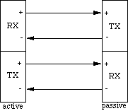
Theoretically, it shouldn't matter whether one or both sides are active: two 20 mA current sources in series are electrically equivalent to a single one. Having both ends active is generally not to be recommended though, if only because this would require crossing the + and - connections instead of following the rule mentioned earlier. Another reason is that at least one end of each link should be electrically 'floating'; this is much easier to realize on the passive side then on the active side.
Example 1
The example shows both ends of a DEC-style cable connecting a computer and a terminal. Notice that the wires in the cable are crossed. Both connectors are male Mat-N-Lok keying plugs.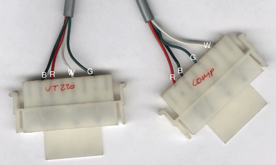
                 terminal               computer
wire color   pin#   function       pin#     function
   red        3        RX-          2          TX-
   green      7        RX+          5          TX+
   white      5        TX+          7          RX+
   black      2        TX-          3          RX-
Example 2