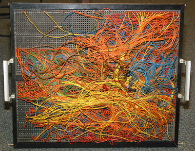
Univac patch panel
UvA Computer Museum catalogue nr 02.14
The contents of the card being processed were stored in a 6*31*31 core stack, together with intermediate results. The sequence of operations was completely determined by the wiring of the plugboard and an electronic program counter, which activated the various parts of the wiring one by one.
The processor used 32 two-address instructions. There was room for 62 program steps. Hence a maximum-size program would require
62*(10+10+5) = 1550 bits of program memory.
The processing results could be directed either to the built-in printer or to an external card-punch.
The theoretical information capacity of the panel can be estimated as follows: Assume that one bit of information is stored by the presence or absence of a patch wire connecting a 'signal' hub *) to a 'ground' (reference) hub. Let a 0-bit be represented by a left-open signal hub. A 1-bit occupies two hubs connected by a patch wire. Then, if there are about as many 0-bits as 1-bits in an information set, the panel's hub pattern can be laid out so as to accomodate 2n/3 bits with n hubs. So in the present case, where n = 80*50 (columns*rows), there is room for about 2670 bits. This agrees well enough with the number mentioned above, though in reality the wire patching reflects the flow of computing (connecting outputs with inputs of computational modules) instead of an abstract bit pattern.
The dimensions of the patchboard shown are 48 * 60 cm.
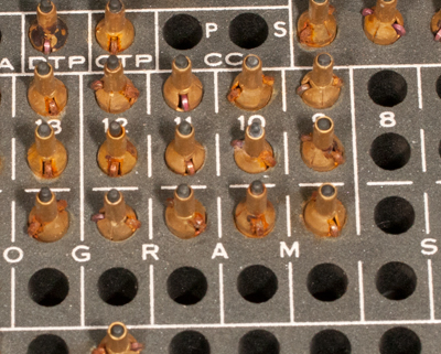
*) Hubs - as they are called in the Univac manuals - are the patchwire connection points, determined by holes in the plastic patch panel. The plugs protruding from the holes (see the illustration) connect with corresponding jacks when the panel is placed into the machine.
This patch panel was donated by Mr. Henrik Bekx. Two similar panels (#12.18a,b, of different wiring and size, respectively) were donated by the heirs of Mr. J.G.C. Mulder, Amsterdam, together with descriptions and programming manuals of the 1004 machine.
