The Williams-tube electrostatic storage device
The electrostatic storage device described below, which was successfully used in several computers before the advent of the magnetic core memory, was devised by F.C. Williams and T. Kilburn in 1948 (University of Manchester, UK). It is probable that they were inspired by ideas which became known during the Moore School Lectures, where electrostatic store devices using CRT-like tubes of special design (internal target plates, multiple electron guns, etc.) were proposed. More or less reliable realizations of these, costing $1500 each were used in the Whirlwind computer around 1950, until they were replaced by core memory in 1953.The Williams design was used in the Manchester Mark I and the commercial Ferranti Mark I (both British machines), and in the IBM 'Defense Calculator' (1951).
In a CRT (in principle a standard oscilloscope type with electrostatic deflection), the electron beam draws a spot of light on the phosphor-covered screen at the XY position where it is directed to by the deflection system. Because each electron hitting the screen releases a number of secondary electrons, a small electric charge builds up on the screen at the spot position, its strength depending on the size and form of the spot. The spot could be, for instance, a sharp dot or an (deliberately) out-of-focus dot. When the beam is switched off, the charge persists for about 0.2 seconds before leaking away; this effect was used for implementing the memory function.

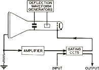
A thin metallic plate P was fitted to the outer surface of the CRT's screen. S and P, separated by the glass of the screen, formed together a small charged capacitor. The electron beam, this time of lowered intensity so as not to disturb the charge distribution, acted as it were a wire connecting S(XY) to 'ground'. P was connected to an amplifier, which produced a voltage proportional to the charge in the 'capacitor' pointed to by the electron beam. A discriminator circuit determined subsequently whether the amplifier output (actually a waveform not a steady voltage) corresponded to a sharp or a blurred dot.
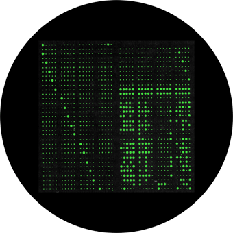
Now bits were stored in random order by writing either sharp or blurred dots (representing logical 0's and 1's, respectively) to appropriate positions on the screen. They were read out - also in random order - by directing the sensing beam to those positions. Notice that there was only a single electron beam in reality. This was switched between writing intensity and sensing intensity by applying appropriate voltages to an electrode in the CRT's electron gun. (The beam direction, on the other hand, depended on the X and Y deflection voltages controlled by the 'addressing' logic circuitry). A typical Williams memory tube accommodated 1300 bits on a 5-inch diameter screen (picture below). Bit access time was of the order of 10 microseconds.

Dot pattern on the screen of a Williams memory tube of a Ferranti Mark I computer.
The pattern represents 32 40-bit numbers and a 20-bit 'page address'. Picture reworked from a picture in [1]
References:
- [1] A.C.D. Haley e.o.: Analogue and Digital Computers. Newnes Ltd., 1960
- [2] K.C. Redmond, T.M. Smith: Whirlwind. Digital Press 1980
- [3] M.R. Williams: A History of Computing Technology. Prentice-Hall 1985
- [4] S. Lavington: Early British Computers. Digital Press 1980
- [5] C.J. Bashe e.o.: IBM's Early Computers. MIT Press 1986
